Spray Wires,Arc Spray Coating,Thermal Arc Spray,Thermal Spray Wire Luoyang Golden Egret Geotools Co., Ltd , https://www.xtcwelding.com


Â
Wireless Bridge Installation and Use
Since all wireless bridge devices are powered by POE, it is extremely important to correctly connect POE power supply boxes, wireless bridges, IP cameras, etc. Wireless bridge devices are designed with outdoor rain-proof and dust-proof design. Waterproof and dustproof treatment.
1. Do a good job of protecting against rain, dust, and insulation. The bridges of wireless bridges, POEs, and network cameras need to be protected from rain and dust. The joints of network cables and wireless bridges generally need to be wrapped with two or three layers of waterproof tape. Try not to expose the crystal heads; network cables and network cameras. The connection part also needs to be wrapped with two or three layers of waterproof tape or insulating tape; all power connectors should be insulated as much as possible.
2. Installation and fixing of wireless bridge equipment. When installing a wireless bridge, you must first fix the bracket. If the bracket is unstable, it will directly affect the stability of the microwave signal transmission. When the wireless bridge is fixed to the bracket, the wireless bridge is fixed according to the fixing method in the following figure. During the installation, since the surface of the bracket is relatively smooth, if the U-shaped clamping code is directly tightened with a nut, it may take a long time, and the outdoor rainwater The surface of the soaked stent will rust and the contact between the U-shaped clip and the stent will loosen. When installing, it is necessary to put a rubber band on the bracket to make contact with the U-shaped clip.
When installing, it is necessary to align the antenna of the device to ensure the sensitivity of the received signal is high and the transmission signal is stable. As shown below:
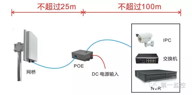
3. Control of network cable and length. The distance between the wireless bridge and the power box or switch should be longer. For the network cable, there are two types of network cable selections, CAT5e (Category 5) or CAT6 (Cat 6). Because the wireless bridge uses POE to provide power, the network cable not only transmits data but also supplies power to the wireless bridge. Therefore, if the network cable is too long or the material quality is poor, it will be seriously attenuated. The connection part of the wireless bridge and POE should use CAT5e or more (try to select the brand cable), and the length should be controlled within 25m. Note: Usually using CAT5e or CAT6 cable to transmit 100m data means that the distance from the LAN port of the POE power supply box to the camera or switch is 100m (as shown in Figure 1); however, the POE power supply box may be installed at a distance because of the different on-site environment. In a distribution center that is remote from the monitoring center or the equipment room, optical fiber transmission is used as far as possible from the POE power supply box to the monitoring center or the equipment room (Figure 2).
(Figure 1)
It is recommended that CAT5e or CAT6 cable should be used for the connection between the wireless bridge and the POE. It is recommended that the cable should not exceed 25m in length to avoid insufficient power supply. The cable between the POE and the network camera, switch, NVR, etc. should not exceed 100m to avoid network failure. Signal attenuation. Figure II:
(Figure 2)
When the POE data transmission port is far away from the monitoring center or equipment room (over 100m), it is recommended to use optical fiber transmission.
There are two main types of POE that are currently recommended. One is a modular POE with an external DC power input, and the other is a stabilized POE with an internal 220V AC input voltage transformer (see Figure 3). Special attention: Regardless of which type of POE is used, the interface definition is uniform. The network port labeled “DATA IN†on the POE can be connected to network cameras, switches, computers and other network devices, and the network marked “P + DATA OUTâ€. Be sure to connect the wireless bridge device to the port. When connecting, be careful not to connect the wrong device.
(Figure 3)
4. The correct connection of network devices such as wireless bridges, POE power supply boxes, network cameras or switches. The POE power supply box generally has three interfaces: a power interface (usually a DC DC input), a POE network port (only used to connect RJ45 ports of a wireless bridge device), a network port or a LAN interface (any Ethernet-based interface may be connected Network devices such as: network cameras, switches, routers, computers, NVRs, etc.).
5. Network cable production standards and their type selection. Currently used cable production standards are generally produced in accordance with the definition of the national standard. It is recommended to use the mainstream T568B line-sequencing standard to make network cables. The standards are as follows:
T568B: White Orange, Orange, White Green, Blue, White Blue, Green, White Brown, Brown
The wireless bridge equipment adopts POE power supply, and it is recommended to use the wire-order production network cable of the national standard T568B. Since all network equipment is an adaptive Ethernet port, it is strongly recommended to use the national standard when connecting a wireless bridge equipment to a POE or switch to a POE. T568B type of direct line (that is, both ends of the cable are the national standard T568B line sequence).
6. Lightning protection. The wireless bridge equipment is generally installed in an outdoor open space and lightning protection measures need to be taken; the equipment itself has a built-in correctly planned IP address of the wireless bridge. Wireless transmission systems built using wireless bridges will use a large number of IP addresses. To avoid conflicts between IP addresses of wireless bridge devices and other devices on the LAN, there are two main solutions: First, separate the networks. Separate the wireless transmission network formed by wireless bridges from other networks (such as office networks and server networks) and use a single core switch. Second, re-plan the IP addresses of devices. Divide the IP address of the wireless bridge device and the network camera and hard disk recorder IP address in different network segments.
Lightning protection circuit, lightning protection ground terminal (GND) is reserved outside the device. The correct method of lightning protection and grounding is as follows: The poles of fixed wireless bridges are generally installed with lightning rods. The grounding terminals of wireless bridges need to use a copper core wire (generally 4 mm2) to connect with lightning conductors to earth.
7. Feeder connector processing. For outdoor high-power bridge equipment, an external antenna needs to be installed because of the long transmission distance, and a feeder connection is needed between the antenna and the equipment. At this time, rainproof and dustproof treatment shall be performed on the joints of all the feeders and the antenna. It is necessary to wrap two or three layers of waterproof tape or insulating tape. Try not to expose the connector part of the feeder to the air.
Software debugging considerations
The debugging of wireless bridge equipment is based on the software interface of IE browser to change or adjust the relevant parameters to achieve the best transmission effect. Since each wireless bridge will be shipped with the corresponding software debugging instructions, this will not be repeated here. Some problems encountered before debugging are explained briefly.
1) The wireless bridge device debugging needs to enter the software debugging interface of the device through IE browser or a third-party browser (such as 360 browser, Sogou browser, etc.). First, you need to change the IP address of the local computer. Make sure that the IP address of the device is on the same network segment as the IP address of the local computer. The specific operation is as follows: Open the "Control Panel" → "Network and Sharing Center" → "Change Adapter Settings" → " "Local connection" → "Properties" → "Internet Protocol Version 4 (TCP/IPv4)" Manually set the computer's IP address.
2) After setting the IP address, enter the IP address of the device in the browser's address bar. Since the first time you enter the debug interface of the bridge device, the browser may not directly pop up the login interface of the device after typing the IP address of the device. An English prompt will appear on the main interface of the browser (Press “Reboot†after all configurations to Enable new setting), as shown below:
For this phenomenon, there is no need to suspect that it is a device problem or a computer problem. The reason for this problem is usually to use a third-party browser to cause compatibility problems. At this time, you only need to click the right mouse button in the browser's address bar to switch between browser modes (compatibility mode or extreme speed mode).
3) Correctly plan the IP address of the wireless bridge. Wireless transmission systems built using wireless bridges will use a large number of IP addresses. To avoid conflicts between IP addresses of wireless bridge devices and other devices on the LAN, there are two main solutions: First, separate the networks. Separate the wireless transmission network formed by wireless bridges from other networks (such as office networks and server networks) and use a single core switch. Second, re-plan the IP addresses of devices. Divide the IP address of the wireless bridge device and the network camera and hard disk recorder IP address in different network segments.